Home

valmis alus autoritasu circuit depicted clock flip flop Pööra lehele kahekordne

Flip-flop (electronics) - Simple English Wikipedia, the free encyclopedia

Draw the circuit symbol of the flip-flop represented by the function table  of Fig. 10.31(a). | Holooly.com
Draw the circuit symbol of the flip-flop represented by the function table of Fig. 10.31(a). | Holooly.com

Voltage waveforms of the signals affected by the clock-overlap in the... |  Download Scientific Diagram
Voltage waveforms of the signals affected by the clock-overlap in the... | Download Scientific Diagram

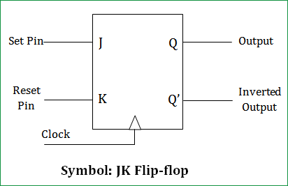
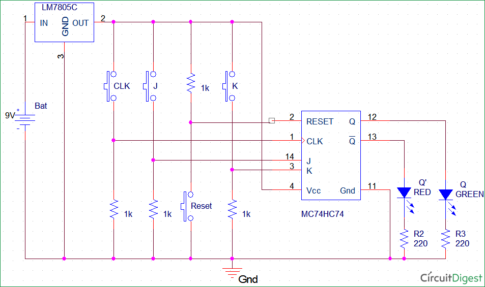
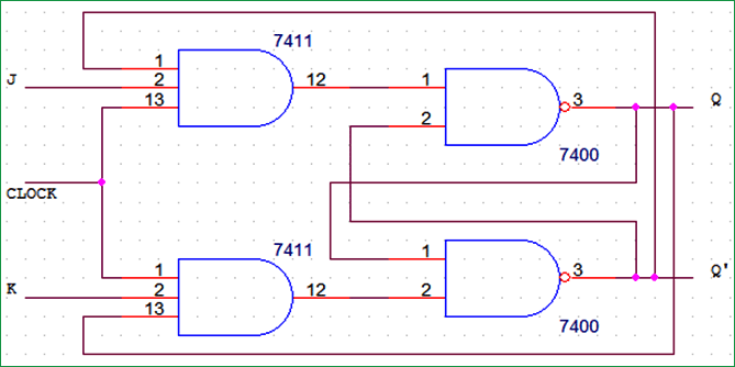
JK Flip Flop [Explained] In Detail - EEE PROJECTS

Draw the circuit symbol of the flip-flop represented by the function table  of Fig. 10.31(a). | Holooly.com
Draw the circuit symbol of the flip-flop represented by the function table of Fig. 10.31(a). | Holooly.com
COUNTERS – Digital Electronics – Dev Guis

JK Flip Flop: What is it? (Truth Table & Timing Diagram) | Electrical4U

JK Flip-Flop Circuit Diagram, Truth Table and Working Explained

JK Flip-Flop Circuit Diagram, Truth Table and Working Explained

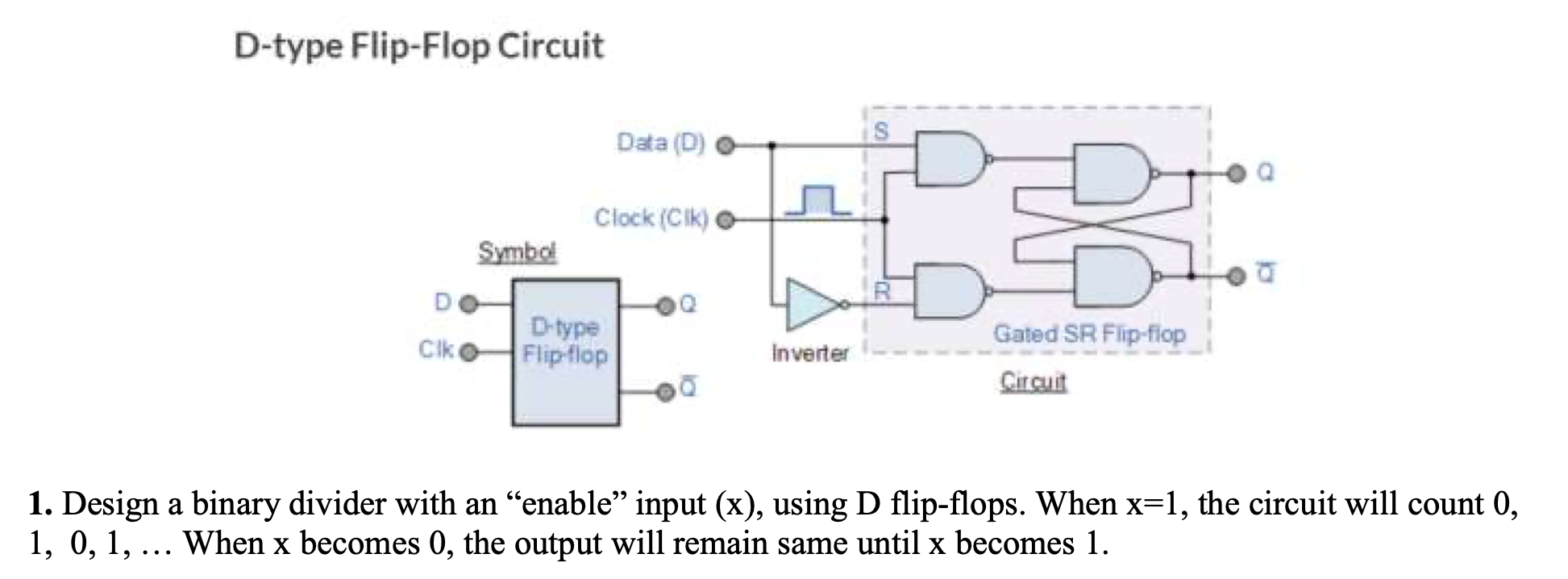
D-type Flip-Flop Circuit Data (D) Clock (Cik) Symbol | Chegg.com

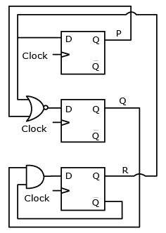
Consider the following circuit involving three D-type flip-flops used in a  certain type of counter configuration.Q.If at some instance prior to the  occurrence of the clock edge, P. Q and R have
Consider the following circuit involving three D-type flip-flops used in a certain type of counter configuration.Q.If at some instance prior to the occurrence of the clock edge, P. Q and R have

1 2 IV. D FLIP FLOP DESIGNS A. TGDFF (TRANSMISSION GATE D FLIP FLOP)... |  Download Scientific Diagram
1 2 IV. D FLIP FLOP DESIGNS A. TGDFF (TRANSMISSION GATE D FLIP FLOP)... | Download Scientific Diagram

JK Flip Flop and the Master-Slave JK Flip Flop Tutorial

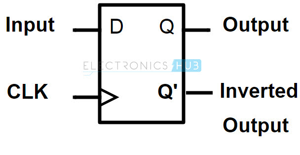
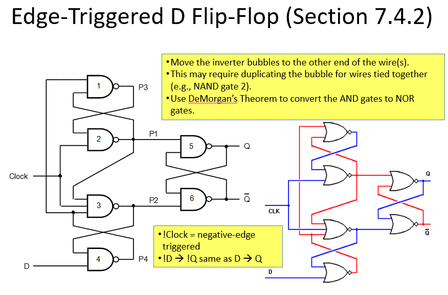
Designing of D Flip Flop

Flip-Flop Circuits Worksheet - Digital Circuits

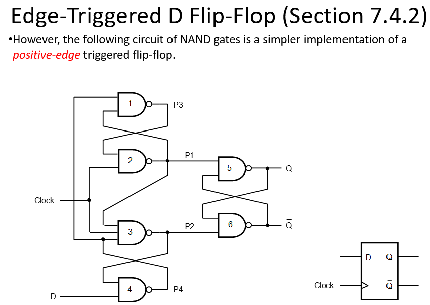
Solved QUESTION 1 Referring to the positive-edge triggered D | Chegg.com

JK Flip-Flop Circuit Diagram, Truth Table and Working Explained

Solved Referring to the negative-edge triggered D flip-flop | Chegg.com

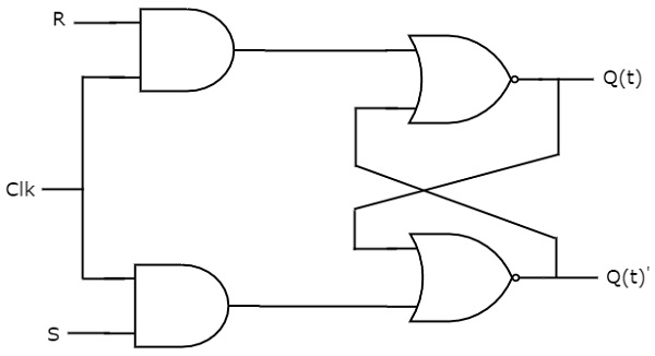
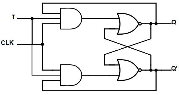
Types of flip-flop circuits explained - RS, JK, D & T - Bright Hub  Engineering
Types of flip-flop circuits explained - RS, JK, D & T - Bright Hub Engineering

Realization of Flip Flops using LabVIEW and MATLAB - PDF Free Download

Lecture 10 Topics: –Sequential circuits Basic concepts Clocks Flip-flops  –SR Flip-Flop –JK flip-flops –D flip-flops Finite state machines  –Moore - [PPTX Powerpoint]
Lecture 10 Topics: –Sequential circuits Basic concepts Clocks Flip-flops –SR Flip-Flop –JK flip-flops –D flip-flops Finite state machines –Moore - [PPTX Powerpoint]

Digital Circuits - Flip-Flops

Virtual Lab for Computer Organisation and Architecture

GATE CSE 2011 | Question: 50 - GATE Overflow

Flip Flop | Truth Table & Various Types | Basics for Beginners

JK Flip-Flop Circuit Diagram, Truth Table and Working Explained

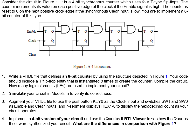
Solved Consider the circuit in Figure 1. It is a 4-bit | Chegg.com

Chapter 6 – Flip-Flops, and Registers